Precision Machining for Aerospace: Requirements & Challenges
A practical guide to aerospace machining: tight tolerances, tough alloys, AS9100 traceability, 5-axis parts, thin-wall control, and FAI inspection.

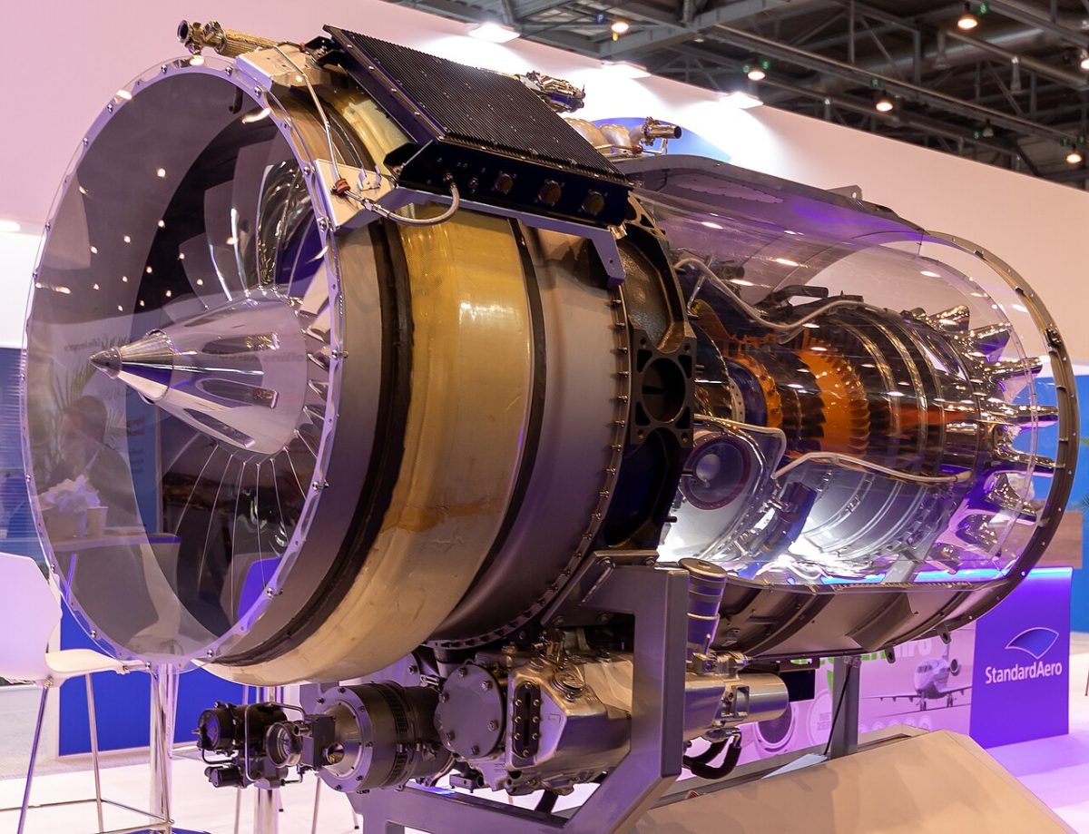
Aerospace components operate in one of the most unforgiving environments engineering has to offer: extreme temperatures, high cyclic loads, corrosive exposure, and zero tolerance for in-service failure. A turbine blade, a structural bracket, or a hydraulic manifold must perform flawlessly for thousands of flight hours. That reality shapes every decision in aerospace precision machining, from the alloy chosen to the inspection report that accompanies the finished part. For engineers and procurement professionals sourcing flight-critical hardware, understanding these demands is the difference between a smooth qualification process and a costly cycle of rejected lots and program delays.
This article examines the core requirements and recurring challenges of precision machining for aerospace: tight tolerances and demanding surface finishes, difficult-to-machine materials, AS9100 quality systems and traceability, 5-axis machining of complex geometries, thin-wall distortion control, and the inspection regime that closes the loop with first article inspection (FAI).
Tolerances and Surface Finish: Where Aerospace Begins
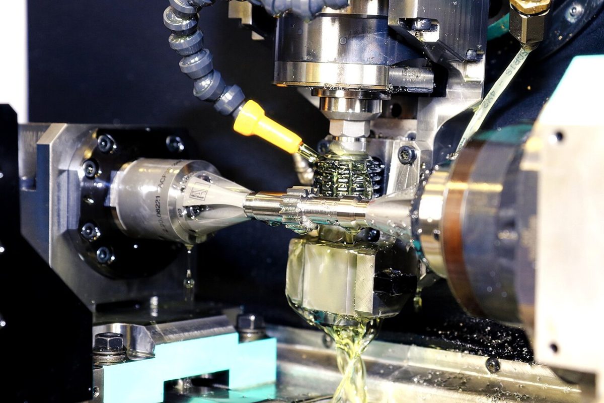
Aerospace machining routinely calls for tolerances far tighter than general industrial work. While a typical commercial part might be toleranced to ±0.1 mm, mating aerospace features, bearing bores, and sealing surfaces are frequently held to single-digit microns. Geometric dimensioning and tolerancing (GD&T) per ASME Y14.5 governs not just size but form, orientation, and position, so flatness, cylindricity, true position, and profile must all be controlled simultaneously.
Surface finish carries equal weight. A rough surface concentrates stress and becomes an initiation site for fatigue cracks, which is unacceptable on components subject to millions of load cycles. Sealing faces, fuel and hydraulic passages, and fatigue-critical fillets often require finishes in the range of Ra 0.4 to 0.8 µm or better, achieved through controlled tool paths, sharp tooling, optimized feeds and speeds, and sometimes secondary finishing operations.
Holding these specifications consistently demands a stable manufacturing environment. Temperature-controlled shops, machines with thermal compensation, rigid fixturing, and in-process gauging all contribute to repeatability across a production run rather than a single good part.
Difficult Materials and Why They Matter
Aerospace selects materials for strength-to-weight ratio, temperature capability, and corrosion resistance, but those same properties make the materials hard to cut. The alloys that perform best in flight are often the ones that punish tooling most aggressively.
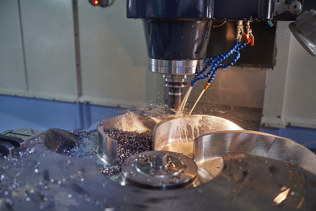
Titanium alloys such as Ti-6Al-4V offer excellent strength-to-weight and corrosion resistance, but they have low thermal conductivity, so cutting heat concentrates at the tool edge rather than dissipating into the chip. Titanium is also chemically reactive at high temperature and prone to work hardening, which together accelerate tool wear and demand conservative speeds with generous, well-directed coolant.
Nickel-based superalloys like Inconel 718 and Inconel 625 retain strength at the high temperatures found in engine hot sections. That same hot hardness means they resist cutting, generate intense heat, and work-harden rapidly, making them among the most challenging materials to machine economically.
Aluminum-lithium alloys reduce weight while improving stiffness compared with conventional aerospace aluminum, which is why they appear in modern airframe structures. They machine more readily than titanium or nickel alloys but still require care around residual stress and thin-wall distortion, particularly on large structural parts.
The table below summarizes the dominant material families and the practical challenges they present on the shop floor.
| Material Family | Typical Aerospace Use | Key Properties | Primary Machining Challenges |
|---|---|---|---|
| Titanium (e.g. Ti-6Al-4V) | Airframe structures, fasteners, engine components | High strength-to-weight, corrosion resistant | Low thermal conductivity, heat at the cutting edge, work hardening, reactive at high temperature |
| Nickel superalloys (Inconel 718/625) | Turbine discs, combustor and hot-section parts | Retains strength at high temperature, oxidation resistant | Hot hardness, rapid work hardening, high cutting forces, accelerated tool wear |
| Aluminum-lithium | Fuselage and wing structures, fuel tanks | Low density, high stiffness | Residual stress relief, thin-wall distortion on large parts |
| Stainless and PH steels | Shafts, fittings, landing gear components | Strength and corrosion resistance | Work hardening, heat management, finish control |
5-Axis Machining of Complex Geometries
Many aerospace parts simply cannot be produced on three axes. Impellers, blisks, structural ribs, brackets with compound angles, and components with deep pockets and undercuts require the simultaneous control of rotational axes to keep the cutting tool oriented correctly to the surface.
Five-axis machining delivers several advantages that matter directly to quality and cost:
- Fewer setups. Machining multiple faces in a single fixturing reduces the cumulative error that creeps in every time a part is re-clamped, improving feature-to-feature accuracy.
- Better tool access. Tilting the part or the head lets shorter, more rigid tools reach difficult areas, reducing deflection and chatter.
- Improved surface finish. Maintaining an ideal lead and tilt angle keeps the cutter engaged at its most effective point, producing cleaner surfaces on contoured geometry.
- Shorter cycle times on complex parts. Consolidating operations cuts handling and queue time between machines.
The trade-off is complexity. Five-axis programming requires robust CAM, collision checking, and post-processor validation, and the machine itself must be calibrated and maintained to hold accuracy through its full range of motion. Skilled programmers and machinists remain central to extracting reliable results.
Thin-Wall and Distortion Challenges
Aerospace design pushes relentlessly toward lighter structures, which means thin walls, deep pockets, and high material-removal ratios where a finished part may retain only a small fraction of the original billet weight. These features fight back against the machinist in two ways.
First, cutting forces deflect thin walls as the tool passes, so the wall springs back after the cut and leaves dimensional error. Second, residual stress locked into the raw stock redistributes as material is removed, warping the part even when the machining itself was accurate.
Experienced shops manage distortion through a combination of strategies:
- Roughing and finishing in separate stages, sometimes with a stress-relief step between, so the bulk of stress redistribution happens before final dimensions are cut.
- Balanced material removal that keeps the part as symmetric as possible during the process to avoid one-sided warping.
- Adaptive and light finishing passes that minimize cutting force on delicate walls.
- Tailored fixturing, including custom soft jaws, vacuum fixtures, and supports that hold the part without over-constraining it or inducing clamping distortion.
- Climbing toolpaths and sharp tooling to reduce heat and force.
Getting this right is as much process engineering as it is machining, and it is one of the clearest differentiators between a supplier that can quote thin-wall aerospace work and one that can actually deliver it.
AS9100, Quality Systems, and Full Traceability
Quality in aerospace is governed by AS9100, the industry standard that builds on ISO 9001 and adds requirements specific to aviation, space, and defense. It emphasizes configuration management, risk management, counterfeit-part prevention, first article inspection, and rigorous control of special processes. An ISO 9001 certified manufacturer has a strong quality foundation; aerospace customers will additionally look for AS9100 alignment and, depending on the application, customer-specific or process-specific approvals such as Nadcap accreditation for special processes like heat treatment and certain surface treatments.
Traceability is the connective tissue of an aerospace quality system. For flight hardware, a manufacturer must be able to trace a finished part back through every step that produced it:
- Material certification tying the raw stock to a mill certificate and heat or lot number.
- Process records documenting machining, special processes, and any deviations or concessions.
- Inspection data capturing measured results against the drawing.
- Calibration records proving the gauges and CMMs used were within calibration.
- Personnel and certification records where special processes require qualified operators.
This documentation chain is not bureaucracy for its own sake. If a problem surfaces in service, traceability lets investigators isolate affected lots quickly and contain risk. For procurement teams, a supplier's ability to produce a complete, organized traceability package is a reliable signal of overall process maturity.
Inspection and First Article Inspection (FAI)
Aerospace parts are verified, not assumed. Inspection spans the full production cycle, from incoming material checks through in-process gauging to final dimensional and visual verification. Coordinate measuring machines (CMMs), optical and laser scanners, surface-finish profilometers, and non-destructive testing methods such as penetrant or ultrasonic inspection all play a role depending on the part and its criticality.
The cornerstone of aerospace verification is first article inspection, commonly performed to the AS9102 standard. An FAI is a complete, independent verification that the first production part conforms to every requirement on the drawing and associated documentation. Each dimension, note, material call-out, and special process is ballooned, measured, and recorded against its specification on standardized forms. A properly executed FAI demonstrates that the entire manufacturing process, not just the part, is capable of producing conforming hardware repeatably.
The table below maps common requirements to the verification activity that satisfies them.
| Requirement | Why It Matters | Typical Verification |
|---|---|---|
| Dimensional accuracy and GD&T | Ensures fit, function, and interchangeability | CMM, optical/laser scanning, hand gauging |
| Surface finish | Controls fatigue life and sealing performance | Profilometer, surface comparison standards |
| Material conformity | Confirms correct alloy and properties | Mill certificates, traceable heat/lot records |
| Subsurface and internal integrity | Detects cracks, voids, and defects | Non-destructive testing (penetrant, ultrasonic, X-ray) |
| Full conformance of first part | Proves process capability before production | First Article Inspection (AS9102) |
What to Look for in an Aerospace Machining Partner
For engineers and buyers, the practical takeaway is that aerospace precision machining is a systems discipline. Capable equipment is necessary but not sufficient; the supplier must also pair it with material expertise, distortion-aware process planning, a mature quality system, and the metrology to prove conformance. When evaluating a partner, it is worth confirming several things:
- Demonstrated experience with the specific alloys your program uses, especially titanium and nickel superalloys.
- Multi-axis capability matched to your part geometry, with validated CAM and programming practices.
- A documented approach to thin-wall and distortion control, including stress relief and fixturing strategy.
- A quality system aligned with AS9100 and, where relevant, accredited special processes.
- Comprehensive traceability and the ability to deliver complete FAI documentation to AS9102.
- In-house or closely controlled metrology, including CMM capacity and surface-finish measurement.
Aerospace tolerances leave no room for guesswork, and the cost of nonconformance, measured in scrapped material, schedule slippage, and qualification risk, is high. The manufacturers that succeed are those that treat machining, materials science, process engineering, and quality assurance as a single integrated capability.
MechPart Pro brings ISO 9001 certified precision manufacturing and broad in-house process coverage to demanding components, supporting customers across more than 40 countries. If you are scoping an aerospace or other high-precision machining project and want to discuss tolerances, materials, and inspection requirements, our engineering team is available to review your drawings and requirements.
Related capabilities

Have a part to make?
Upload your CAD for a detailed quote and free DFM feedback within 24 hours.