CNC Turning vs. Milling: Choosing the Right Process
A practical guide for engineers and buyers on how CNC turning and milling differ, which part geometries each suits, and when to combine them.

Computer numerical control (CNC) machining covers a family of subtractive processes that remove material from a solid blank to produce finished parts. Two of these processes dominate metalworking shops worldwide: turning and milling. Although both rely on cutting tools and programmed tool paths, they differ fundamentally in how the cutting motion is generated. Understanding that difference is the key to specifying the right process, controlling cost, and achieving the tolerances your application demands.
This guide explains how each process works, the part geometries it favors, what to expect from surface finish and tolerance, and how modern mill-turn machines blur the line between them. Whether you are designing a component or sourcing one, knowing where each process excels will help you make better engineering and procurement decisions.
How CNC Turning Works
In turning, the workpiece rotates while a single-point cutting tool moves against it. The blank is clamped in a chuck or collet on a spindle, the spindle spins it at high speed, and the tool advances along and across the axis of rotation to remove material. Because the part itself provides the cutting motion, turning naturally produces shapes that are symmetric about a central axis.
A turning center, or lathe, can perform a range of operations on the rotating blank:
- Facing to create a flat surface perpendicular to the axis
- Outer diameter (OD) turning to reduce and shape the external profile
- Boring to enlarge and finish internal diameters
- Drilling along the centerline of the part
- Grooving and parting to cut recesses or separate the finished part
- Threading to produce internal or external screw threads
Turning is fast and efficient for round work. Because the tool stays in continuous contact with a steadily rotating surface, it removes material at a high rate and tends to leave a consistent finish.
How CNC Milling Works
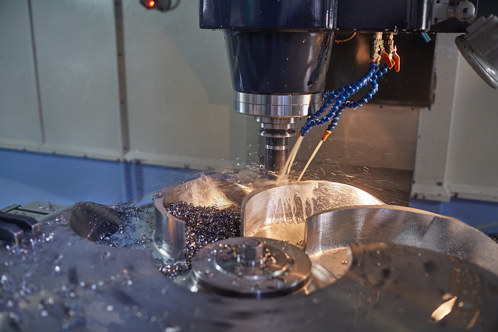
Milling reverses the relationship: the cutting tool rotates while the workpiece is held stationary on a table, and the table (or the tool head) moves the part through the cutter along multiple axes. A rotating multi-tooth tool such as an end mill or face mill shears away material as the part traverses beneath or beside it. This arrangement gives milling enormous geometric freedom.
Three-axis machines move the part in X, Y, and Z. Four- and five-axis machines add rotation, allowing the tool to approach a feature from many angles in a single setup. Typical milling operations include:
- Face milling to create broad flat surfaces
- Pocketing to remove material from enclosed cavities
- Slotting and profiling to cut channels and contoured edges
- Drilling, tapping, and reaming of holes in any face
- Engraving and 3D contouring of complex surfaces
Milling shines wherever a part has flat faces, pockets, slots, holes on multiple sides, or sculpted three-dimensional surfaces that no rotation-based process could create.
Rotational vs. Prismatic Geometry
The single most useful question when choosing between the two processes is: is the part rotational or prismatic?
Rotational parts favor turning
A rotational, or axisymmetric, part can in principle be generated by spinning a profile around an axis. Shafts, pins, bushings, rollers, threaded fasteners, hydraulic fittings, flanges, and many valve bodies fall into this category. For these, turning is almost always the most economical and accurate choice because the geometry matches the way the machine cuts.
Prismatic parts favor milling
A prismatic part is built from flat faces, blocks, ribs, bosses, and pockets rather than a single axis of revolution. Housings, brackets, manifolds, plates, gearbox cases, and structural mounts are typical examples. These require the multi-directional access that only milling provides.
Many real components are hybrids. A cylindrical shaft may need a flat, a keyway, or a cross-drilled hole; a milled housing may include a precision bore. These mixed-geometry parts are exactly where process selection becomes interesting, and where combined machining (covered below) earns its keep.
Surface Finish and Tolerance Considerations
Both processes are capable of tight tolerances and good surface finishes, but they behave differently because of how the cutting motion is generated.
Turning tends to produce excellent surface finishes on cylindrical features. The tool maintains continuous, single-point contact with a uniformly rotating surface, which yields a regular, repeatable finish. Concentricity, roundness, and diameter tolerances are inherently easy to hold because all the turned features share one axis established in a single setup.
Milling uses interrupted cutting: each tooth on the rotating cutter enters and leaves the material repeatedly. This can leave visible tool marks and slight scalloping, particularly on contoured 3D surfaces, though fine finishing passes, sharp tooling, and well-tuned feeds and speeds produce smooth results. Milling's strength is positional accuracy of features relative to one another across multiple faces.
For both processes, achievable tolerance depends on material, part size, rigidity, tooling, and how many setups are required. A general rule worth remembering: every additional setup introduces a potential source of positional error. Reducing setups is one of the most effective ways to tighten tolerances, which is a major reason combined machining has become so popular.
Turning vs. Milling at a Glance
| Attribute | CNC Turning | CNC Milling |
|---|---|---|
| What moves | Workpiece rotates; tool is fed against it | Tool rotates; workpiece is moved through it |
| Cutting tool | Single-point tool | Multi-tooth rotating cutter |
| Best part geometry | Rotational / axisymmetric | Prismatic / multi-sided / 3D |
| Typical parts | Shafts, bushings, pins, fittings, threaded studs | Housings, brackets, manifolds, plates, cases |
| Cutting action | Continuous | Interrupted |
| Surface finish strength | Smooth cylindrical surfaces | Flats, pockets, complex contours |
| Tolerance strength | Concentricity, roundness, diameter | Feature position across faces |
| Axes (typical) | 2 axes (plus driven tools on advanced lathes) | 3 to 5 axes |
Mill-Turn Machines: When the Line Disappears
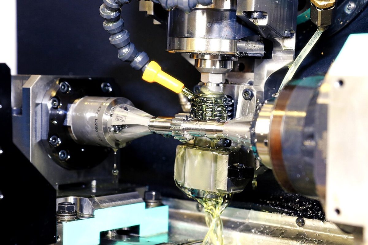
Modern mill-turn machines, also called multitasking or turn-mill centers, combine both capabilities in a single platform. They start with a turning spindle that rotates the workpiece, but they also carry driven (live) tooling and, on more advanced models, a full milling spindle that can index and lock the workpiece in position. The machine can turn a diameter, then stop rotation, switch to a rotating cutter, and mill a flat, drill an off-axis hole, or cut a keyway, all without removing the part.
The advantages are significant:
- Fewer setups. Complex parts are finished in one or two operations rather than transferring between separate lathes and mills.
- Better accuracy. Because features are machined while the part is held in a single reference position, positional errors from re-fixturing are minimized.
- Shorter lead times. Consolidating operations reduces handling, queue time, and the risk of damage between machines.
- Lower labor and handling cost for medium- and high-complexity components.
The tradeoff is that mill-turn machines and their programming are more sophisticated, so they are most cost-effective for parts that genuinely benefit from combined operations rather than simple geometries that one process handles well on its own.
When to Combine Processes
Choosing a single process is straightforward for purely rotational or purely prismatic parts. The decision gets nuanced when a component mixes the two. Consider combining turning and milling, whether on a mill-turn machine or across separate machines, when:
- A fundamentally rotational part needs flats, slots, keyways, or cross-holes
- A part requires both a precision bore and milled mounting faces that must stay accurately located relative to that bore
- Tight concentricity must be preserved between turned and milled features, making a single reference setup essential
- Production volume justifies the programming investment to eliminate manual transfers
- Lead time is critical and consolidating operations removes days of queue and handling
Practical guidance for designers and buyers
A few habits make process selection smoother and parts cheaper to produce:
- Design to the process. If a feature can be made rotational, it will usually be cheaper to turn. If a part is mostly prismatic, avoid unnecessary cylindrical callouts that force extra operations.
- Specify tolerances only where they matter. Over-tight tolerances on non-critical features drive cost without adding function, because they may demand additional finishing passes or setups.
- Flag the critical datum relationships. Telling your manufacturer which features must stay concentric or accurately located helps them choose the right setup strategy, often pointing to a mill-turn solution.
- Share the application, not just the drawing. Understanding load, fit, and finish requirements lets a manufacturer suggest the most efficient route.
Conclusion
Turning and milling are complementary, not competing, processes. Turning is the natural choice for rotational parts where the workpiece spins against a single-point tool, delivering excellent cylindrical finishes and concentricity. Milling is built for prismatic and complex geometries, using a rotating cutter to access multiple faces and sculpt three-dimensional features. Mill-turn machines unite both, reducing setups and tightening accuracy for hybrid parts. The right decision starts with one question about geometry and ends with a clear-eyed look at tolerance, finish, volume, and lead time.
If you are weighing the best process for an upcoming component, the engineering team at MechPart Pro can review your drawings and recommend an approach that balances quality, cost, and delivery. As an ISO 9001 certified manufacturer serving customers in more than 40 countries, we work across turning, milling, and combined machining to match the process to the part.
Related capabilities

Have a part to make?
Upload your CAD for a detailed quote and free DFM feedback within 24 hours.