5-Axis CNC Machining: When You Need It and Why
A practical engineering guide to 3-axis vs 5-axis CNC machining - the geometries that demand it, the accuracy and setup benefits, and the cost trade-offs.

Choosing the right CNC machining strategy is one of the earliest and most consequential decisions in bringing a precision component to production. For many parts, a conventional 3-axis mill is the most economical and entirely sufficient choice. For others—those with sculpted contours, deep undercuts, or tight tolerances across multiple faces—5-axis machining is not a luxury but a requirement. Understanding where that line falls helps engineers design smarter parts and helps procurement teams avoid both overspending on simple geometry and underspecifying complex work.
This article breaks down the practical differences between 3-axis and 5-axis CNC machining, the part features that genuinely require five axes, and the accuracy, lead-time, and cost factors that should drive the decision.
Understanding the Axes: 3-Axis vs 5-Axis
A CNC machining center moves a cutting tool relative to a workpiece along defined axes. The three linear axes—X, Y, and Z—describe left-right, front-back, and up-down motion. Nearly all milling work is built on these three.
A 3-axis machine moves the tool along X, Y, and Z only. The workpiece stays fixed in a single orientation, and the cutter approaches it from above. This covers a huge proportion of everyday parts: flat faces, pockets, holes, slots, and profiles that can all be reached from one direction.
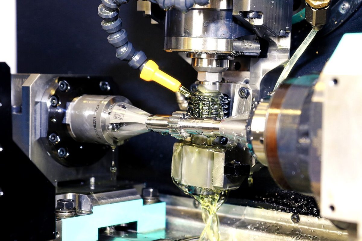
A 5-axis machine adds two rotational axes to the three linear ones. These rotary axes—commonly labeled A, B, or C depending on the configuration—allow either the tool head or the worktable (or both) to tilt and rotate. The result is that the cutting tool can approach the workpiece from virtually any angle within the machine's envelope. This is what makes complex, multi-sided geometry achievable in a single setup.
Two Modes of 5-Axis Work
It is worth distinguishing between two ways 5-axis capability is used, because they serve different purposes:
- 3+2 (positional) machining: The two rotary axes orient the part to a fixed compound angle, then lock. Cutting then proceeds as conventional 3-axis milling in that orientation. This is ideal for reaching multiple faces of a prismatic part without manual re-fixturing.
- Continuous (simultaneous) 5-axis machining: All five axes move at once during the cut, allowing the tool to follow sweeping, organic surfaces. This is essential for impellers, turbine blades, and other free-form contours.
Many parts that seem to "need 5-axis" actually only need 3+2 positioning, which is faster to program and less demanding on the machine. True simultaneous machining is reserved for genuinely sculpted surfaces.
Geometries and Features That Require 5-Axis
Certain design characteristics push a part beyond what a 3-axis machine can produce in a single, accurate operation. Watch for these:
- Undercuts and negative draft: Features that curve back under themselves cannot be reached by a tool descending vertically.
- Multiple machined faces at compound angles: When five or six sides of a part require precision features, a 3-axis approach demands repeated re-fixturing, each introducing alignment error.
- Free-form and sculpted surfaces: Aerodynamic blades, medical implant contours, and mold cavities with flowing surfaces require the tool to remain tangent to a constantly changing surface normal.
- Deep cavities with limited tool access: Tilting the part lets a shorter, more rigid tool reach deep features, reducing chatter and improving finish.
- Ports, channels, and angled holes: Bores that enter the part at oblique angles are far easier to produce when the part can be tilted to present the hole axis to the spindle.
If a part can be fully machined from one or two orthogonal directions, 3-axis is usually the right answer. The moment a feature requires the tool to come in at an arbitrary angle, 5-axis enters the conversation.
Accuracy and Reduced-Setup Benefits
The most compelling argument for 5-axis machining is often not the geometry it unlocks but the accuracy it preserves. Every time a part is removed from a fixture and re-clamped for a new operation, a small positional error is introduced. Across several setups, these errors stack up as tolerance drift between features that were cut in different orientations.
5-axis machining addresses this directly:
- Single-setup machining: Holding the part once and reaching multiple faces means all features share a common datum reference. True position and feature-to-feature tolerances improve because they are no longer subject to re-fixturing error.
- Better surface finish: Orienting the part to keep the tool at its optimal cutting angle—and using the side of the tool rather than just its tip—produces smoother surfaces and can reduce or eliminate hand finishing.
- Shorter, more rigid tooling: Tilting the part to bring features closer to the spindle allows shorter tools, which deflect less and cut more accurately.
- Fewer fixtures: Reducing the number of dedicated fixtures lowers tooling cost and removes a source of variation between production runs.
For parts where dimensional consistency across many features is critical, the reduction in setups is frequently the deciding factor, independent of whether the geometry strictly requires five axes.
Cost and Lead-Time Trade-Offs
5-axis capability is more expensive on a per-hour basis. The machines carry a higher capital cost, programming is more complex, and skilled 5-axis programmers and operators command a premium. CAM programming for simultaneous 5-axis work also requires careful collision checking and toolpath verification, adding engineering time before the first chip is cut.
However, comparing only the hourly rate is misleading. The relevant comparison is the total cost and total lead time to a finished, in-tolerance part. A component that needs four separate 3-axis setups—each with its own fixturing, alignment, and inspection—can easily cost more and take longer in total than the same part produced in a single 5-axis operation, while also carrying a higher risk of stack-up error and scrap.
A reasonable decision framework looks like this:
- Choose 3-axis when the part is largely prismatic, features are accessible from one or two directions, and tolerances between faces are forgiving.
- Choose 3+2 positional 5-axis when a prismatic part has features on many faces or at compound angles, but no free-form surfaces.
- Choose simultaneous 5-axis when the part has true sculpted contours, or when single-setup accuracy across complex geometry is non-negotiable.
3-Axis vs 5-Axis: Side-by-Side Comparison
| Factor | 3-Axis CNC | 5-Axis CNC |
|---|---|---|
| Axes of motion | X, Y, Z (linear) | X, Y, Z plus two rotary axes |
| Tool access | Primarily from above; one direction at a time | Almost any angle within the work envelope |
| Typical setups per part | Often multiple re-fixturings for complex parts | Frequently a single setup |
| Feature-to-feature accuracy | Subject to re-fixturing stack-up | Shared datum improves true position |
| Best-suited geometry | Flat faces, pockets, holes, simple profiles | Undercuts, compound angles, free-form surfaces |
| Surface finish on contours | May require additional finishing | Optimal tool engagement, smoother finish |
| Programming complexity | Lower | Higher; collision checking required |
| Hourly machine cost | Lower | Higher |
| Cost on complex parts | Can rise with many setups | Often lower total cost despite higher rate |
Typical Applications
5-axis machining is concentrated in industries where geometric complexity and tight tolerances intersect:
Aerospace
Turbine blades, impellers, blisks, structural brackets, and housings frequently combine free-form aerodynamic surfaces with demanding material specifications such as titanium and nickel-based superalloys. Single-setup machining is valued here both for accuracy and for the difficulty of re-fixturing hard-to-hold shapes.
Medical and Dental
Orthopedic implants, prosthetic components, and surgical instruments often feature anatomically contoured surfaces and require excellent finish and repeatability. 5-axis machining produces these organic geometries while maintaining the tolerances regulatory documentation demands.
Energy, Automotive, and Tooling
Pump and compressor components, complex manifolds, and high-performance automotive parts benefit from the reduced setup count. In moldmaking, 5-axis machining of cavities and cores allows shorter tools to reach deep features cleanly, improving both finish and tool life.
Making the Right Call for Your Part
The decision between 3-axis and 5-axis machining should be driven by the part's actual requirements, not by a general preference for capability. Start by asking three questions: Can every feature be reached from one or two directions? Are the tolerances between features tight enough that re-fixturing risk matters? Does the part have any genuinely free-form surfaces or undercuts? The answers usually point clearly toward the appropriate process.
It also helps to involve your manufacturing partner during design rather than after. Small adjustments to a part—relaxing a tolerance, adding a small radius, or reorienting a feature—can move a job from costly simultaneous 5-axis to efficient 3+2 work, or even back to 3-axis, without compromising function. Early design-for-manufacturing review is one of the most effective ways to control cost.
At MechPart Pro, our engineering team reviews part geometry and tolerance requirements to recommend the most cost-effective machining strategy for each component. If you are weighing 3-axis against 5-axis for an upcoming project, our team is glad to review your drawings and advise on the best approach.
Related capabilities

Have a part to make?
Upload your CAD for a detailed quote and free DFM feedback within 24 hours.